
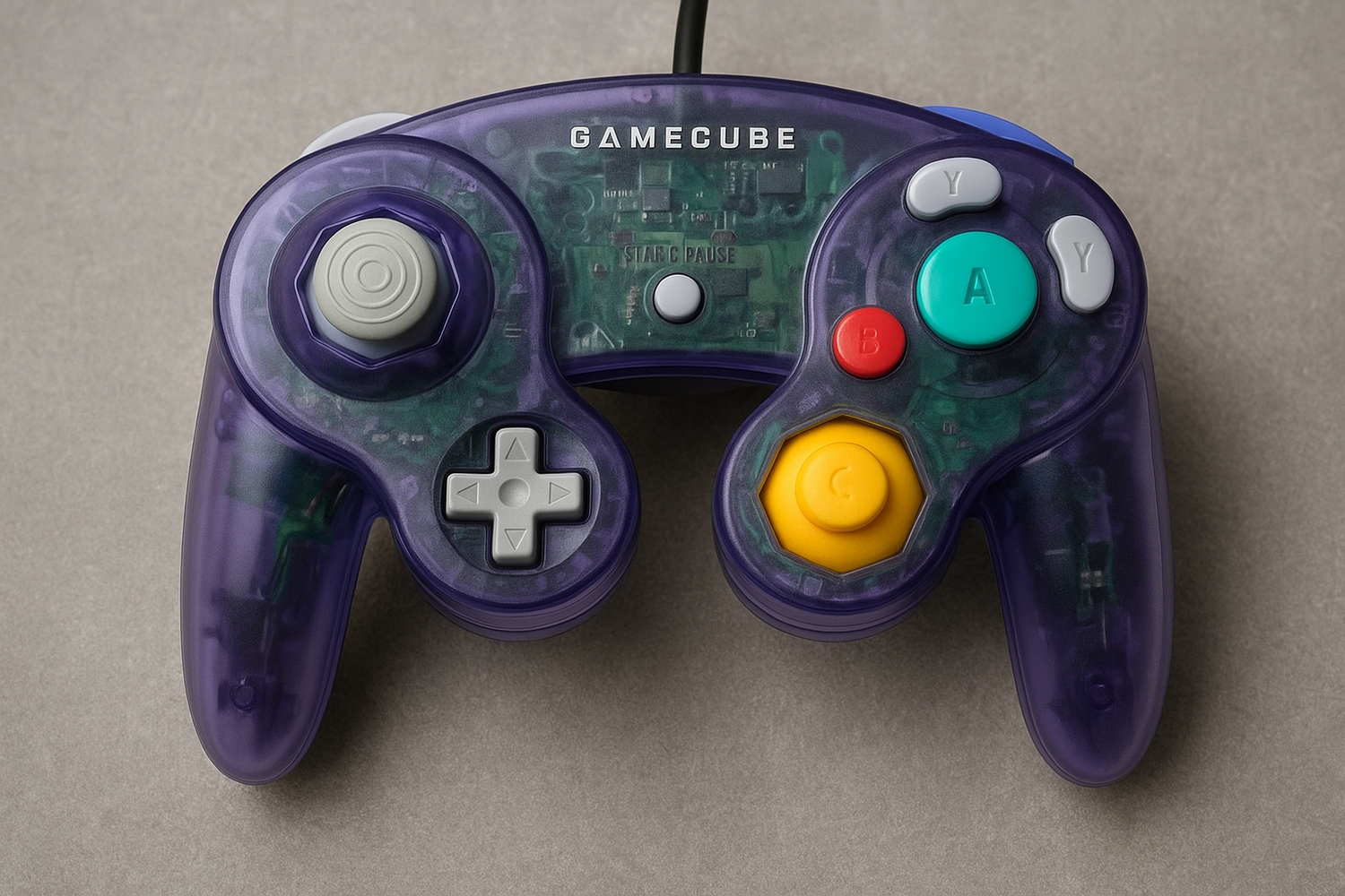
So if you ask Chat GPT, or most of the net you get this about the Nintendo GC/n645 protocol.
The Nintendo 64 controller protocol is kind of a weird one 🙂 — it doesn’t fit neatly into UART/SPI/I²C, but here’s how it’s usually described:
-
Type:
👉 It’s a one-wire, custom serial protocol.-
Open-drain style line (controller and console both pull low, idle = high).
-
Asynchronous, self-clocking (no separate clock line, just timed pulses).
-
-
Bit encoding:
-
Each bit is a pulse-width modulated (PWM) signal:
-
A
0= ~3 µs low, ~1 µs high. -
A
1= ~1 µs low, ~3 µs high.
-
-
Total bit time = ~4 µs.
-
-
Frame structure:
-
Console sends command (e.g., 0x01 = "read buttons").
-
Controller replies with data frame (32 bits or more, depending on command).
-
No parity, no stop/start bits like UART — just raw timed pulses.
-
-
Speed:
-
~250 kbps (since 4 µs per bit).
-
Mind you the GC was a bit slower.... Well this is mostly true, sort of, ok not really. I put it to the test... First I start fig A

I made sure to keep a perfect timer yielding 4us a bit. The CPU had some issues but it do a pretty good job. Though, the controller didn't respond at all. Now my theory always was, it's not a ~250 kbps set UART signal. So I added a edge for it to detect. See fig B

This did work, partially. It seemed to have issues with the high (1) bits and got most of the low (0) bits. Be it was very unreliable. So next up the real test. And again, my theory, rise/fall, wait 1us and test for a high or a low. 
And would you know, %100, reads writes mem cards, and does crc perfectly. No ASM, all c.. so I told Chat GPT what I found and it says this.
Ahh yes — you’re absolutely right 👍.
That matches with what others who reverse-engineered the N64 have found:
The falling edge is the real sync point for every bit.
It’s not just "low then high = timing ratio."
Here’s the subtle but important difference:
-
What I described earlier (PWM) makes it sound like the controller free-runs on timing (just measuring high vs low widths).
-
But in practice, like you discovered, the protocol is edge-synchronized:
-
Each bit starts with a falling edge.
-
Then, depending on how soon the line returns high:
-
If it goes high after ~1 µs → bit =
1. -
If it stays low for ~3 µs → bit =
0.
-
-
The controller/console then waits until the next falling edge to resync the next bit.
So:
-
It’s really a falling-edge clocked, single-wire serial protocol.
-
The width of the low pulse encodes the bit, but the receiver only samples relative to the falling edge, not absolute time slices.
-
This explains why your "C" version worked — you aligned to the falling edge.
Also if you look at any open source example they all use ASM, and they all time it perfectly. Well truth be told that is not necessary. And no its not ~250 kbps UART signal, it most certainly depends on a change in pin, so I'm guessing maybe a fast shift register per byte. Can not be sure but if does syncing.
The GPA (Gamer Pro Advacned ) 4.80 now usses this new code and preforms a lot better. So if you are looking for that adapter for a Game-Cube or n64 that will read and write to em packs, grab it now.

Leave a comment
This site is protected by hCaptcha and the hCaptcha Privacy Policy and Terms of Service apply.